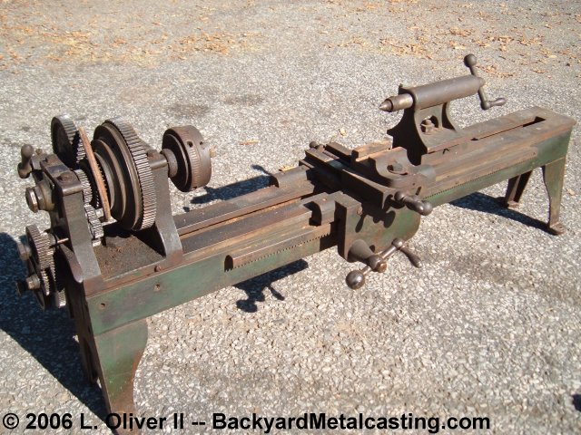
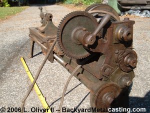
Here is an overall view of the uncleaned lathe. It is about one meter (39 inches) long has a swing of 8-1/4" (4-1/8" center height for the British enthusiasts) and has 22" between centers, or 24" without the chuck on the spindle. I call it an 8 X 20 lathe just to make things easier. The total weight is about 70 pounds. Click photo for larger view
Here is how I received the lathe. It was being used as a wood lathe. I was very happy to see (when I picked up the lathe) that the apron hand wheels and all the other saddle parts were in place! The auction photo was horrible and I thought the parts may have been removed. An improvised wood lathe type tool rest was installed by drilling and tapping a bolt hole in the compound slide. I unscrewed the bolt and took that crap off.
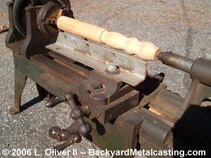
Here is the carriage assembly complete with apron, cross slide and compound slide. The only thing missing is a tool post and cutting bit. There is a little bit of backlash in the cross slide screw. Notice that this lathe has no feed screw for the compound slide. But the bolt on it does allow it to rotate for angled work. There are two threaded holes in the flat top of the cross slide. It seems that this "compound slide" is a bolt on attachment which can be replaced with other bolt on attatchments such as a milling attachment.
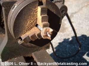
Here is a homemade spur center that was used for the wood turning setup. Three "teeth" were cut in a ring of brass and it was threaded onto a sharpened shaft. The center is then held in the three-jaw chuck. The chuck is 3" diameter.
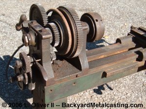
In this view you can see the headstock with it's pulley and gear assembly. The pulley is designed for a round belt of about 3/8" diameter, one of which is on there. Notice the two holes in the bed below the headstock. I'm guessing that some nameplate from the manufacturer or distributor was rivited there sometime in the past. Unfortunetly I don't know the manufacturer. But I've read that British lathes tended to have flat beds (as this one does) while American lathes had triangular ridges the length of the bed. Maybe that is a clue. Hopefully I'll learn more after the lathe is cleaned.
An identifying clue? The 3-jaw chuck has "DFW Co" Stamped into each jaw. And the chuck's face has some words stamped into the front. It is very tiny and poorly stamped. Only the top half of the letters are there and it's not a result of surface wear or damage, just poor stamping. But it appears to say; "D F WU*TON MACH The "*" represents an unrecognizable letter. I examined this with a magnifying glass and even one of those jeweler's eyepieces but the letters just aren't fully stamped in the metal. I'm guessing "MACH" is short for machine. and "CONN" is short for Connecticut. There is also an "A X" stamped on each jaw and on the rear of the chuck's outer rim. The jaws are also numbered one though three.
NEW LONDON CONN
This small lathe even has a backgear for extra low spindle speeds. Notice also that this lathe has the change gears so it can possibly cut threads (As of right now I haven't the foggiest notion how to do that). But you may find it interesting that the lead screw is actually on the backside of the lathe.
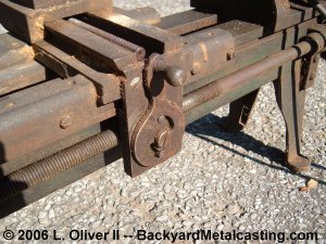
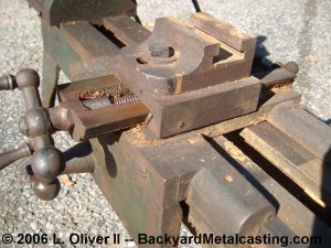
In the center of the photo here you'll see a knob and lever assembly. This is located on the back side of the carriage and is the mechanism for engaging the split nut or half nut (whatever you want to call it) on the leadscrew for possibly thread cutting or power feed. With this here I wonder if I could still add a taper turning attachment.
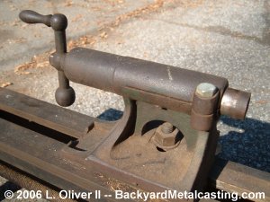
Here's the tailstock. The ram slides forward and back very smoothly. I'm not sure what the taper in the ram is but it matches the headstock spindle taper. It's larger than a #1 morse taper and smaller than a #2.
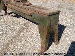
The bases on this lathe are very basic. It is nothing like some of the ornate cast bases I've seen on other vintage lathes. You can see that the bed is very narrow. It's only 3-3/4" wide. Note the toothed rack along the front side of the bed. The saddle assembly slides across by gears riding this rack like a "rack and pinion" assembly. More from this project very soon.