Go to section: Obtaining the lathes | Pillaging a third lathe | Homemade countershaft |
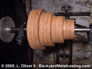
Here is the countershaft pulley that turns the flat belt and ultimately turn's the lathe's headstock pulley. I made it from disks of plywood since I didn't have a lathe capable of machining one from metal. The the pulley's side there is a steel flange bolted to the pulley which contains a setscrew to secure the pulley to the shaft.
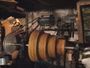
Here is a view of the motor installed on the countershaft. The motor is on a hinged plate so the motor's weight tensions the belt.
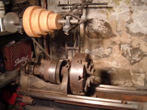
Here's a view of the 12" 4-jaw chuck installed.
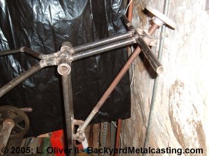
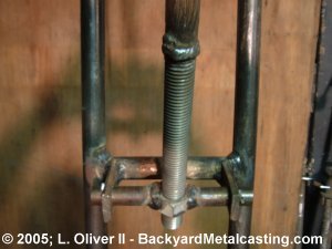
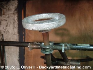
The belt is tensioned by the raising or lowering of the countershaft pulley. The diagonal rod is mounted in two pivoting joints. So as the handwheel is turned the lower threaded portion of the rod screws into or out-of the lower joint. As it screws in or out, the upper joint is carried along the rod and either pulls or pushes on the countershaft's pulley mount bracket. This creates a "see-saw" motion to raise or lower the pulley.
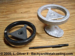
The handwheel is a simple aluminum casting that I made. The pattern was a plastic handwheel from a discarded Delta brand table saw.
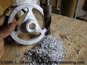
After cutting off the gate I drilled out the hole to fit the tensioning rod. An incredible amount of chips for just a 3/4" diameter hole.
This is the lower joint. It is made from a 3/4" nut welded to two rods so the nut can pivot in the joint to keep the rod at the correct angle as the countershaft raises and lowers. As you can see the bottom section of the tensioning rod is a section of threaded rod welded to solid round rod.
Here is the upper joint. This is just like the lower one except that the threads are drilled out of the nut so the rod can spin freely in it. The washers and cotter pins keep the joint at the designated position on the rod and this tilts the pulley bracket in the "see-saw" motion.
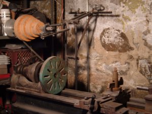
Here is the countershaft in position. A flat belt is still needed to run the lathe.
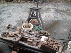
Here is the lathe dissasembled on my pallet jack. I decided to sell it because I was tired of working on it. I'd rather just buy a small lathe and be able to use it rather than keep working on this.
Go to section: Obtaining the lathes | Pillaging a third lathe | Homemade countershaft |